Module 2
Unit 1: Familiarisation with Prism

Here is an of how to navigate from the Patient panel to the Volume editor, the Point editor and the Structure set panel. How to navigate from the Beam panel to the Leaf and Portal editor (MLC panel) is shown .
(Note: The MLC panel is only available if a machine type with a multi leaf collimator is selected.)
The Patient panel contains additional functions not covered in Module 1. These functions are shown in .
-
Loading the phantom:
-
Select Patient “17 Carpet 4, Carlos”, Case 1 from the archive by using the Select-button.
-
Delete the content of the textbox in the Patient panel, enter your initials in the first line and checkpoint the patient.
-
Load the image study associated with the patient “Carpet 4, Carlos” by pressing the Image study-button. In the you can see how the images are loaded in the background.
-
Open the by clicking on the Anatomy/points-button to inspect the axial slices you have just loaded by clicking on the film strip images or the arrow buttons.
-
Use the magnification slide to view the phantom.
-
-
Insert structures: In the "Other tools"-menu on the Patient panel you can find a function to import structures for the current case, the .
-
Select the structures for the patient "Carpet 4, Carlos" from the 'available structure sets' and import only the structure "BODY".
-
Contouring: In the :
- Select the organ "BODY" from the menu bar on the right hand side.
-
Check if the BODY-structures fit the outline of the phantom in different slices (i.e. for different Z-values) (Note: In the filmstrip, contours might not be shown in the correct position.) .
-
Vary the gray scale window and level of the image displayed for optimal viewing.
- Add an organ.
-
We now define the cylindrical structure at the bottom of the phantom (see Figure 1) as an organ at risk (OAR) and contour it.
To create the contour: - Select the organ you have added before.
- Change the name
of the organ to "OAR" and set the
colour of the organ to red.
- Draw the structure by adding points with the left mouse-button.
- Press the Accept-button
to close and store the
structure.
- Go to slice -5.0. Use the Copy NP-function and check if you have to modify the contour from slice to slice. Do not forget to press the Accept-button after each change to store your changes. Do this for slices Z=-5.0, -4.0, -3.0, -2.0, -1.0, 0.0, 1.0, 2.0, 3.0, 4.0 and Z=+5.0.
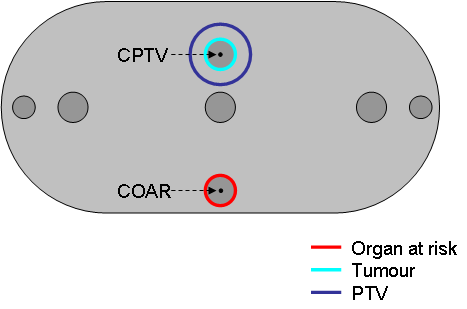
Figure 1: Positions of PTV and OAR in the phantom
- Add a tumour.
-
Define the round structure at the top of the phantom as tumour (see Figure 1) and contour it in the slices Z=-4.0, -3.0, -2.0, -1.0, 0.0, 1.0, 2.0, 3.0 and Z=+4.0.
-
Change the name of the tumour to "TUMOUR" and set the colour of the tumour to cyan.
-
Add a target (Planning Target Volume - PTV) around the tumour. Press "Add a target” and select the “Tri-Linear expansion”-mode from the list. This function adds a PTV with a uniform margin around the tumour. Select a 1.0 cm margin! Change the target name to PTV and set the colour of the PTV to blue.
-
For each organ, you can choose whether its electron density is used in dose computation or ignored. The default value is 0 g/cm³, corresponding to air.
-
Change the settings for the organ “BODY”, so that it is used in dose computation. Press the button labelled "Ignore in comp." to change it to "Use in comp.". The electron density is set to 1.0 g/cm³, corresponding to water.
-
Close the Volume editor, go back to the Patient panel and add the comment "/contoured" behind your initials in the textbox. Save the comment in pressing Accept cmts and checkpoint the case.
-
Adding points of interest: The can be used to define dose points.
-
Add points of interest in slice Z=0.0 as shown in Figure 1. (Don't forget to save the changes by pressing the Accept-button).
- In the centre of the PTV.
- In the centre of the OAR.
- On top, bottom, left and
right side of the PTV.
- Label the centre points "CPTV" and "COAR" (see Figure 1) and save the changes by pressing the Accept-button. (Use the right mouse button to change the labels; see General Control Functions )
- Label all other points appropriately.
-
Go back to the Patient panel and add a comment like "/Points added" in the first line of the text field. Checkpoint the patient.
-
-
Beam shaping: Add a plan and a beam to the case. Choose the therapy machine "SL20A-6MV-MLC". This machine has a multi-leaf collimator (MLC). Open the . In the display area, you can see the structures of this case in a Beam's-Eye-View (BEV).
-
Remove the BODY contour from the display by using the Objects-button.
-
Modify the red contour representing the beam aperture, so that it encloses the PTV. Press the Accept-button to apply your changes.
- Press Set leaves to adjust the MLC leaves to the contour.
-
- Close all panels except the Patient panel. Add a comment like "/Beam added" in the first line of the text field. Checkpoint the patient.
| << Previous Page |
Top of the Page |
Next Page >> |